


Cables, Connectors and Analog Audio Signal Types Explained
Posted: 24 March 2014
Synopsis: A guide to analog audio signal types and the different connectors and cables used to transfer them between devices. Written with an empathises on real life situations, this is an ideal resource for musicians, beginner sound technicians and anyone involved

Cables, Connectors and Analog Audio Signal Types Explained
It is true that an increasing amount of effects processing and post production work is being done ITB (inside the box / computer), however a lot of musicians still prefer to be actually creating music on real instruments and microphones. This is where the humble analog audio cable comes in, linking your favourite instrument and amp through to your mixing desk or recording device. Analog audio cables are going to be with us for some time yet, and if you are a musician, beginner sound technician or involved in audio or music in some way, getting your head around the different connectors and signal types can be a handy piece of knowledge, and it's all probably simpler then you may think. Below I provide a simple outline for the common types of audio cables and connectors found in the music scene, and the signal types running through them.
Jump to section:
Connectors
Analog Audio Cables
Audio Signal Types
Common Mistakes
Connectors
Common Connector Types
When you look at any musical instrument, effects unit or mixing desk, you are bound to see at least one, if not numerous audio connectors. There are 3 main connector types that you are seeing across all this equipment; in perhaps both their 'Male' and 'Female' gender types, these are the ¼" Jack, the XLR 3pin connector, and the RCA plug. The fact that we may refer to them as a jack, connector or plug is practically meaningless and due only to preference Although the technical electrical characteristics may differ slightly, in terms of everyday use they are all just ways of transferring an electrical signal from a "conductor" (copper inside an audio cable) into a device or vice versa.
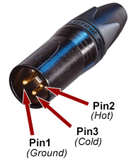
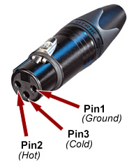
The connector itself, like the audio cable, has "conductors" that carry the signal through the length of the connector shell and into the device circuitry. Often these conductors in the cable are referred to as "pins". The amount of pins in an audio connector determines how many separate signals it can transfer. Let's have a look at the conductors or pins of the 3 main audio connector types.
Pinout Diagram - XLR, 1/4", RCA
| XLR - Male | 1/4" - Male | RCA - Male |
 |
 |
 |
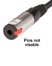
| XLR - Female | 1/4" - Female | RCA - Female |
 |
 |
 |
| A.K.A - cannon plug - 3pin plug |
A.K.A - guitar jack - 6.5mm / 6.35mm connector - phone plug - TS (Tip, Sleeve) connector |
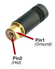
A.K.A - phono plug |
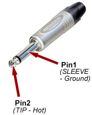
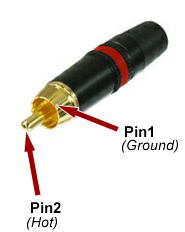
As you can see, the XLR connector has 3 pins while the ¼" and RCA connector have 2 pins. Note that the ¼" jack connector forms its 2 separate pins by using a thin strip of insulation (black ring) around the connector, thus isolating the signals between the top (tip) of the connector and the larger bottom section (sleeve). The RCA and 1/4" TS are are "mono" connectors, meaning they can only carry 1 audio signal.
Other Connectors
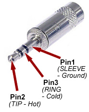
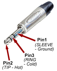
There are two other commonly found connectors which are also of the 'jack' style design. One mostly used in the pro audio industry and the other mostly in consumer devices. Both of these connectors have 3 conductors / pins, and thus have one additional black insulation ring around the connector enabling them to carry a 3rd signal on the one jack. A jack connector capable of carring 3 signals is refered to as a TRS connector.
Pinout Diagram - 1/8" TRS, 1/4" TRS
| 3.5mm TRS - Male | 1/4" TRS - Male |
 |
 |
| A.K.A - 1/8" jack - Mini-Jack - ipod connector |
A.K.A - Stereo Jack - 6.5mm / 6.35mm TRS - balanced jack |
They look similar because they are, with the only practical difference being size. Signal transfer works exactly the same in both. They also go by numerous different names, with all meaning the exact same thing. Both TRS varieties are known as "Stereo" connectors, meaning they can carry 2 audio signal.
Pinout Diagram - 1/8" TRRS
|
Another style of 'jack' plug has recently found its way into common occurrence through the rise of smartphones, the TRRS connector. This connector features an extra black insulation ring allowing it to carry a 4th signal on the one connector. This is useful on phones and smaller laptops because it allows for a headphone output (left + right), as well as a microphone input (unbalanced, mono) to be included all on the one connector. Nokia originally created the TRRS connector to have the microphone signal transferred down the '2nd Ring', though Apple decided to through a curve ball to the accessories market and changed the mic signal transfer to the 'Sleeve' on their devices. It should be a noted that TRRS connector can carry 3 audio signals, as well as ground connection. |
3.5mm TRRS - Male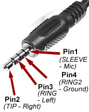 |
Analog Audio Cables
Two Main Types
|
There are really only two main categories of analog audio cables used extensively in music and pro audio. We know these as our "guitar lead" and "microphone cable". The main difference between them being the number of separate conductors they contain. In the case of a cable, a conductor is a strand of copper wire, covered with a jacket of insulating plastic (PE), often referred to as a 'core'. Audio cables also consist of another copper wire that wraps around the outside the insulated conductors or core, this wire also conducts a signal but is not generally referred to as a conductor, but rather the "ground wire", "drain wire" or "ground shield". Here you can see a guitar lead as a single conductor, and a ground shield. While a microphone cable has two conductors and a ground shield. A ground shield never carries an actual analog audio signal so is not itself critical to sound, however its job is to perform an electrical 'grounding' between the 2 devices and to shield the inner conductors from external electrical interference (hence being wrapped on the outside).
|
Balanced Microphone Cable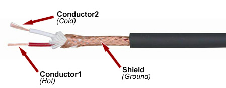 |
Guitar Lead Cable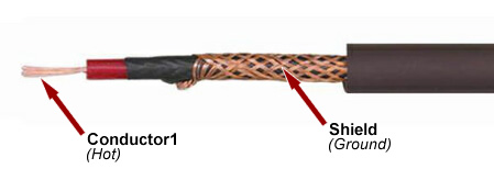 |
Joining Connectors to Cable
Now you are ready to see how the common cables and connectors are joined together and how it is actually possible to make a cable with any combination of the discussed connectors. All you need to do it match the pins on the connector, to the pins/conductors in the cable. Directly below are three common cables types with a pinout diagram showing how the connectors and cable are joined.
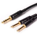
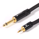
| Guitar Lead - 1/4" to 1/4" Jack TS - Mono Instrument Cable |
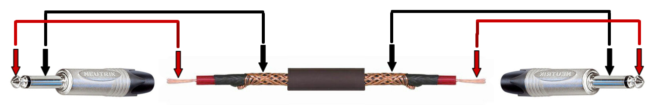 |
| 1/4" Jack TS to RCA Plug - Mono Instrument Cable |
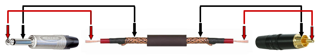 |
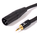
| XLR(m) Connector to 1/4" Jack TRS - Stereo/Balanced Mic Cable |
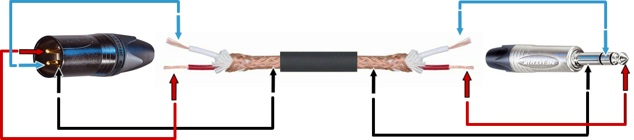 |
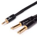
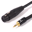
| XLR(f) Connector to 3.5mm Jack TRS - Stereo/Balanced Mic Cable |
-to-3-5mm-TRS-Wiring-Pinout-Small.jpg) |
In the above examples, all pins inside the connectors have been connected to conductors in the cable. Though you should also note that not all pins have to be connected to individual conductors, some cables require two pins to be combined or "shorted". Below you can see examples of common cables that feature this type of wiring.
| XLR(f) Connector to 1/4" Jack TS - Mono Instrument Cable |
-to-1-4-Jack-Mono-TS-Wiring-Pinout-Small.jpg) |
With the above cable, the 1/4" jack is mono and therefore a balanced signal is not possible, meaning mono instrument cable can also be used for this cable. Usually a device such as a microphone, expects there to be an electrical connection on pin 3 of the XLR(f) connector to carry the 'cold' signal. To ensure proper function with the device, we can satisfy the electrical expectation of the device/ by simply shorting pin 3 to pin 1 inside the XLR connector. The result is the 'cold' signal is fed into the ground.
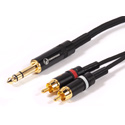
| 3.5mm Jack TRS to XLR(m) Connector- Stereo/Balanced Mic Cable |
-Stereo-to-Mono-Wiring-Pinout-Small.jpg) |
The 3.5mm mini jack to XLR male cable above is different to the previous example, in that we are also combining signals that are carrying the actual audio. This cable is used to combine a "stereo" headphone jack output, say on a laptop, ipod or smartphone, into a "mono" XLR input on a mixer or powered speaker. As an XLR input on such equipment is almost always a "balanced", simply sending the "stereo" signal using individual conductors will result in the input trying to "balance" the "stereo" signal. By connecting both the Tip and Ring of 3.5mm jack connector to pin 2 on the XLR connector, we create 'mono' mix of the left and right channels from the headphone output. Again we short Pins 1 to 3 inside the XLR connector to satisfy electrical expectation.
Audio Signal Types
There are 3 main signal types that our common types of audio cables and connectors carry. The common names for these signal types are "guitar level", "mic level" and "line level". This is where knowledge is needed to ensure you are using the correct cable, and signal processing device (if required), to connect between any of the common connectors. Just because a device has an input or output connector that matches your cable and instrument / device, it does not mean that the signals types match.
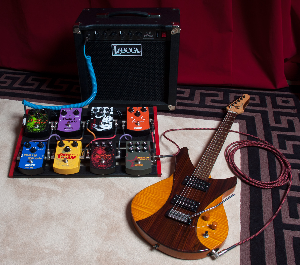
1. Guitar Level / Hi-Z
|
Outputted from an electric guitar (or acoustic with pick up), and also the same type of signal that guitar pedals and guitar amps are set up to receive. It is sometimes referred to as a Hi-Z signal, meaning High-Impedance. Guitar equipment is always made with ¼" mono jacks for carrying guitar level signals. When running cables between your guitar, effects board and to your amp; you should be using the same type of cable – the guitar lead, or referred to as a patch cable in shorter lengths. Guitars output a "mono unbalanced" signal. Meaning they output only 1 audio signal while having a 'ground' connection. |
 |
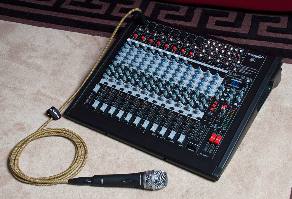
2. Mic Level / Low-Z
|
Microphones output a 'mono', 'balanced' signal, which is unique in the way that it can be used to cancel out noise / interference picked up along a length of cable. Leaving the technical stuff aside, a balanced signal merely consists of 2 audio signals and requires 2 conductors to carry the signal, thus a 'microphone cable' is required to carry the signal. 3 pin XLR connectors are found on all microphones and microphone inputs on mixing desks, preamps and recording devices and are all pretty much standard for mic level signals. A mic level signal is sometimes referred to as 'Low-Z', meaning 'low impedance'. |
 |
X. Signal Processors
|
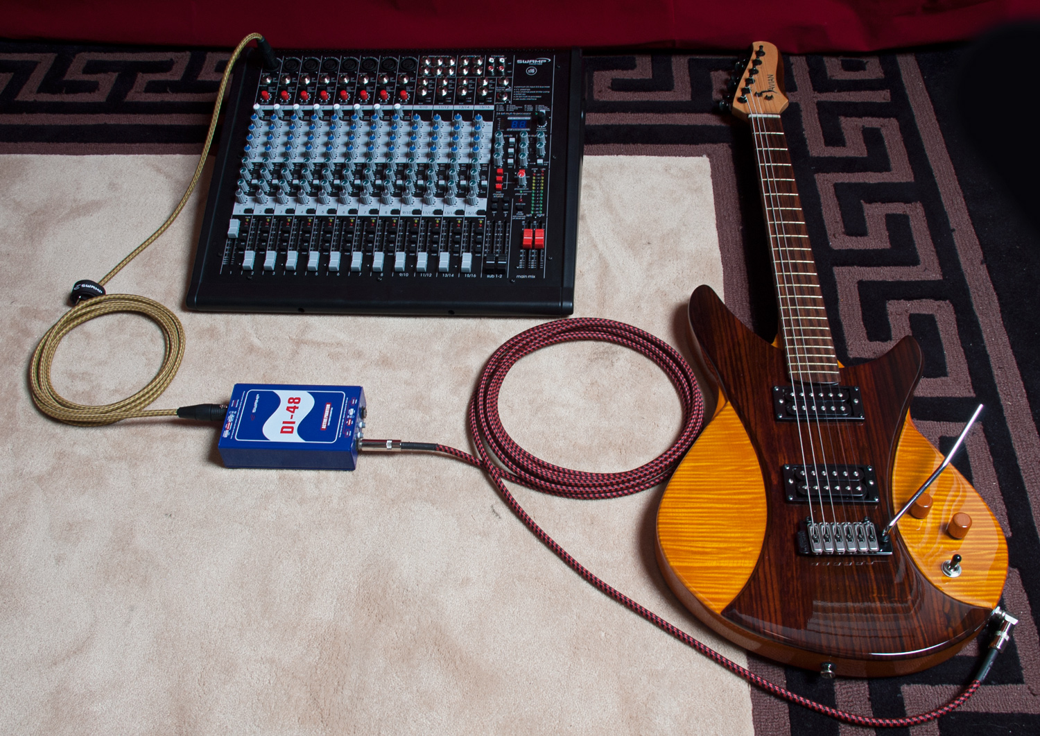
Now might be the right time to bring up signal processors and there role in the life of a musician or sound technician. Say you're an acoustic guitarist playing a live show and the sound tech tells you he wants you to use a DI box so he mix your signal on this FOH (front of house) mixing desk. What he wants to do is take your 'Guitar Level' signal and then input it into his "Microphone Level" input on the mixer. By getting you to plug you guitar lead into the DI box, he converts the guitar level signal into 'balanced' mic level, and can then use a 'balanced' microphone cable to carry the signal to his mixer. As there may be some distance to the mixer, having the signal 'balanced' for the longer cable run is ideal. |
 |
|
Alternatively you might want to plug a microphone into a guitar amp for practice at home. In this case you are doing wanting to do the opposite to the above example, and what you need is a "impedance transformer" that converts the mic level signal into guitar level. Plugging a low-z microphone into a hi-z guitar input will work, however the signal quality is diminished and there is a noticable volume drop. |
3. Line Level
|
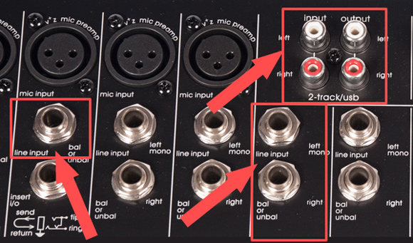
In you are looking at a mixing desk or similar device and wondering what ins and outs are line level, the easy way is to eliminate those that are a mic level input (XLR inputs) and then typically, the rest are 'line level'. The ¼" jack inputs on each input channel of the mixer are usually line level, with only a small number of mixing desks having these as 'guitar level' (sometimes switchable). When a ¼" input on a mixer is line level, is it also a ¼" TRS jack socket built to accept a 'balanced' line level signal. |
 |
|
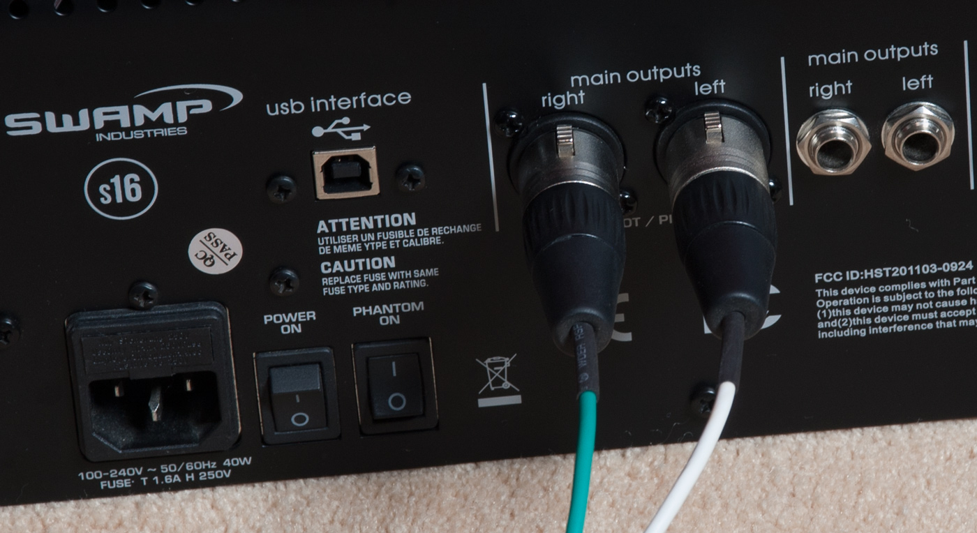
The outputs on a mixer are typically 'balanced' line level and are often offered in both XLR and ¼" output variations. This really just gives you the option of using a cable with XLR or ¼" TRS connectors. Or you can use both outputs at once. |
 |
|
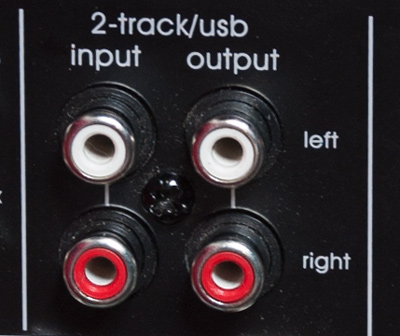
RCA connectors are always unbalanced and almost exclusively carry unbalanced line level signals. An RCA connector has only 2 conductors, thus can carry only 1 audio signal + ground. It's common to find them in pairs, outputting mono left and right audio signals (stereo). |
 |
XX. Headphone Level
|
The type of signal outputted from a headphone jack socket can be seen as being similar to a 'line level' signal though can actually be quite a bit stronger depending no how loud you turn it up. This means you can plug a cable between a headphone output on your laptop, smart phone or ipod and a line level input and get decent results for music playback without the need for signal processors. It should be noted, that a headphone level signal is just a weak form of a 'Speaker Level' signal. Though not discussed and relevant to this article, a speaker level signal connects a power amplifier to passive speaker and is carried by a speaker cable. We see less and less of speaker cables these days due to many amplifiers and speakers being combined into the same unit; such as a powered/active speaker or guitar combo. In these cases the 'speaker cable' is not visable, but is still used for the internal wiring of the amp to speaker. |
 |
XXX. Stereo Signals
An important topic arises here due to the fact that a headphone output produces what's known as a 'stereo' signal. Stereo is simply 2 separate audio signals, one carrying the Left channel and one the Right channel. Since the 60's music Producers have mixed music in stereo, increasing or decreasing volume on the left and right channel to give effect. When connecting a headphone output into a line input, consider a cable that ends in dual ¼" jacks where each carries left of right signal.
 |
 |
 |
 |
Common Mistakes
Guitar Level into Line Level
It's a common crime we have probably all committed at some point; plugging a guitar lead straight into a ¼" jack line level input on a mixing desk. The plug will fit fine, the jack will say input, and it will work. However you are connecting between 2 different signal types with no signal processor in the middle. In this example you have an impedance mis-match and will lose some signal clarity and overall volume. The suggestion here is, get a DI!
Line Level into Microphone Level
As discussed, the main outputs on mixing desks are typically line level, designed to be connected to a line level input on a powered speaker or amplifier. Though with the rising popularity of power speakers, many featuring both an XLR mic level and XLR line level input, it is possible to fall into the trap of connecting the line level signal into the mic input. Doing this will mean the signal is sent through another mic preamp, likely leading to distrortion and clipping of the mic input. Remember a 'XLR mic cable' can carry both a mic level or line level signal.
Stereo into Balanced
In you are connecting a stereo signal, be that from a 3.5mm headphone output or other device, into a mono 'balanced' mic or line level input on a mixer or powered speaker, then you are going to have combine the left and right audio signals into a single mono signal. Otherwise you will lose either the left or right signal from you audio, or even worse trick the input into trying to 'balance' a 'stereo' signal (weird sounds occur..)
 |
 |
 |
_2x1-4(f)_SM_30cm.jpg) |
Conclusion
With these basic concepts in mind, it is possible to navigate the once daunting maze of connectors and sockets that litter not only gear in the musical and pro audio scene, but also commercial and home entertainment devices. Master the knowledge above and you can see how simple it really is to connect one piece of analog audio equipment to another, by simply using the right cable and connector.


 Pre-Order


